in Digital Logic edited by
11,490 views
37 votes
37 votes

The following arrangement of master-slave flip flops

has the initial state of $P, Q$ as $0, 1$ (respectively). After three clock cycles the output state $P, Q$ is (respectively),

  1. $1, 0$
  2. $1, 1$
  3. $0, 0$
  4. $0, 1$
in Digital Logic edited by
11.5k views

4 Comments

Thanks for replying !!

In asynchronous counter the output of 1 FF is given to other FF and I thnkt because of that it's Asynchronous .

Pleaee Correct me if I am wrong.
0
0

Yes, you are right that in asynchronous counter the output of 1FF is given to other FF but the output is given as the  Clock of other FF while in the synchronous we have same clock.

Please Correct me if I am wrong.

1
1
After three clock cycle output states P,Q is 1,0 (no change in answer)
0
0

5 Answers

60 votes
60 votes
Best answer

Here, clocks are applied to both flip flops simultaneously. Outputs for $3$ cycles will proceed as follows:

  • When $11$ is applied to $JK$ flip flop it toggles the value of $P.$ So, output at  $P$ will be $1.$
  • Input to D flip flop will be $0$ (initial value of P).  So, output at $Q$ will be $0.$

    $JK$ flip flop it toggles the value of $P.$ So, output at  $P$ will be $0.$

  • Input to D flip flop will be $1$ (current value of P) . So, output at $Q$ will be $1.$
  • $JK$ flip flop it toggles the value of $P.$ So, output at  $P$ will be $1.$
  • Input to D flip flop will be $0$ (initial value of P)  so output at $Q$ will be $0.$

So, answer is A.

edited by

4 Comments

@laxman Patel how did you form the the expression for PNext....please elaborate
0
0

@Doley

In general $:Q_{Next} = J\:\overline{Q} + \overline{K}\:Q$

1
1

In the first clock itself when the clock is high:

As we know that clock time is generally smaller than the delay due to FF, when the output of J-K becomes 1 before the clock goes low, the output of D will change to 1. So at the end of cycle one, the output seems to become 1 1.

Similarly after clock cycle two and three output will become: 0 0 and 1 1 respectively.

@Lakshman Bhaiya kindly correct me.

0
0
20 votes
20 votes

now when clock is aplied J= 1 and K=1 then (it do complement of P) i.,e output at p = 1 and at same time FF D has input 0 so it change Output Q as ) only [ on D-FF input = output]

SO output will be p= 1 and Q= 0 

[ keep in mind both FF work at same time dont wait for 1st complete then second will start].

2 Comments

@sittian  hopw you got it now.

0
0
You are not getting this ia synchronous ckt I.e. clock is not present on any FF . Both FF work at together here .. Check clock input properly..

Input to D comes from JK FF not
0
0
4 votes
4 votes
first find the next state for jk-ff and d-ff  which is p(n+1)=not(p) and q(n+1)=d=p
given in question p=0 and q=1 so next state for p=1 and q=0
so a is ans
3 votes
3 votes

-> As there is Master Slave configuration, 1st flipflop will respond to the positive edges and the 2nd flipflop to the negative edges.

-> As the given Flipflops are synchronous,(clock is simultaneously given to both FFs) $Q$ responds according to immediate values of $P$.

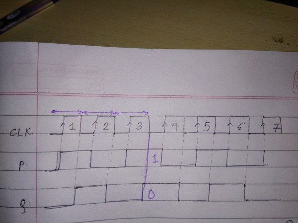
-> Thus, after 3 cycles, as shown in the diagram, $P = 1$ and $Q=0$ 

Answer:

Related questions