in Digital Logic edited by
6,390 views
18 votes
18 votes

Consider the synchronous sequential circuit in the below figure
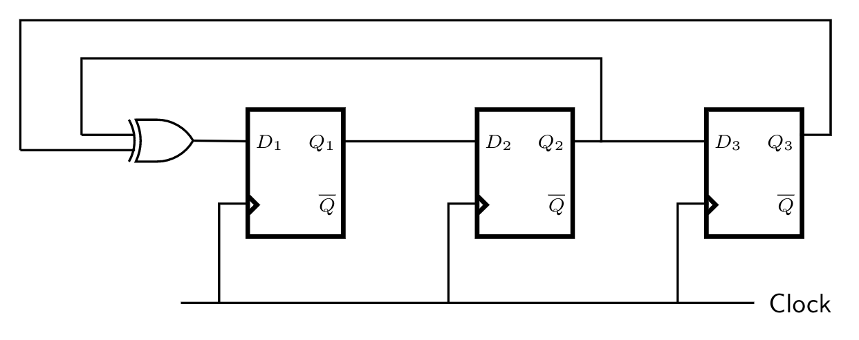
Draw a state diagram, which is implemented by the circuit. Use the following names for the states corresponding to the values of flip-flops as given below.

$$\begin{array}{|l|l|}\hline \textbf{Q1}  &  \textbf{Q2} & \textbf{Q3} & \textbf{State} \\\hline  \text{0} & \text{0} & \text{0} & \text{S$_0$} \\\hline  \text{0} & \text{0} & \text{1} & \text{S$_1$} \\\hline – & – & – & – \\\hline   – & – & – & – \\\hline – & – & – & – \\\hline  \text{1} & \text{1} & \text{1} & \text{S$_7$} \\\hline \end{array}$$

in Digital Logic edited by
6.4k views

3 Comments

where is B part?
2
2
2
2
Q1 = Q2_prev XOR Q3_prev

Q2 = Q1_prev

Q3 = Q2_prev
1
1

2 Answers

22 votes
22 votes
Best answer

State Diagram : 

$S_{7} \to  S_{3} \to S_{1}\to S_{4} \to S_{2} \to S_{5} \to S_{6} \to S_{7}$

b. Given the initial state $S_{4}$, $S_{0}$ state will not be reachable. If the system enters $S_{0}$ state then $Q_{0}$$=$$Q_{1}$$=$$Q_{2}$$=0$ and after that it will stay in $S_{0}$ state indefinitely  and can't go to any other state. 

edited by
by

4 Comments

@Arjun sir in this questions it is not mentioned which flipflop to consider as MSB. In most of the questions it is given like $Q3Q2Q1= 000$ which tells which bit has to be treated as MSB.

If question is regarding which mod counter it is, it doesn't matter but if they ask output after x clock cycles then there is problem :(.

0
0

 @  by the description of states S0,S1... we can say that they have considered Q3 as LSB and Q1 as MSB

0
0
It is a MOD $7$ counter.
1
1
31 votes
31 votes
Caption

Related questions