Answer : D ( +ve Triggered D – FF)
(Note: it should be done by analyzing all inputs and seeing how is it working, i.e., writing all input cases and Clock cases in a table, but as the paper is lengthy such a short analysis is not bad.)
The number of inputs for the circuit = 1
(observe it is not a combinational circuit rather it is a sequential circuit since it depends on the previous state of the circuit)
and by seeing options, the circuit should be one of $T - FF$ or $D - FF$, either $+ve$ or $-ve$ $ Edged $.
so we should see how it behaves for the input on the $+ve$ edge of the clock and the $-ve$ edge of the clock.
If it $Toggles$ the input provided in one of the {$+ve$ / $-ve$} edges, then it is $T-FF$
else if it $Latches$ the input provided in one of the {$+ve$ / $-ve$} edges, then it is $D-FF$.
else if it $Latches$ or $Toggles$ on provided input for both, then it is neither $D - FF$ nor $T - FF$.
(since there is no option, we can assume it's not and the circuit is one of T or D for sure)
let's mark the circuit for checkpoints as
$i$ as input,
$Q_{1}$ for the output of the first MUX and
$Q_{0}$ for the output of the second MUX (left to right as shown in the image below)
the equations of MUX outputs are as follows :
$Q_{1}^{+}$ = $CLK . Q_{1} + \overline{CLK} . i $
$Q_{0}^{+}$ = $CLK . Q_{1} + \overline{CLK} . Q_{0} $
checking for 2 cases of the clock:
(refer to the diagram/image provided for a better explanation)
Case 1: Clock goes from 0 -> 1 (+ve edge)
when the Clock is 0 : input $i$ will be in $Q_{1}$
after the clock transitioned to 1 : input $i$ will be moved to $Q_{0}$ ( which is the output)
Case 2: Clock goes from 1 -> 0 (-ve edge)
when the Clock is 1 : input $i$ will not be selected in to $Q_{1}$ (it has previous Q_{1} only, not input)
after the clock transitioned to 0: input $i$ will be moved to $Q_{1}$ ( not the output )
Image :
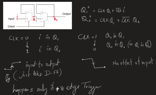
Conclusion:
we can observe that the input $i$ is in the output only when the clock is transitioned in $+ve$ edge and it doesn't toggle the input rather it latches it,
Hence we can conclude it as an $Positive$$-Edge$ $Triggered$ $D -$ $FlipFlop$ (option D)