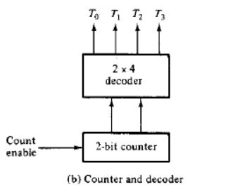
Add four 2-input AND gates to the circuit of the figure. One input in each gate is connected to one output of the decoder. The other input in each gate is connected to the clock. Label the outputs of the AND gate as $P _0,P _1,P _2, and P _3$. Show the timing diagram of the for P outputs.