in Digital Logic edited by
12,611 views
33 votes
33 votes

Consider the circuit given below with initial state $Q_0=1, Q_1=Q_2=0$. The state of the circuit is given by the value $4Q_2+2Q_1+Q_0$

Which one of the following is correct state sequence of the circuit?

  1. $1, 3, 4, 6, 7, 5, 2$
  2. $1, 2, 5, 3, 7, 6, 4$
  3. $1, 2, 7, 3, 5, 6, 4$
  4. $1, 6, 5, 7, 2, 3, 4$
in Digital Logic edited by
12.6k views

7 Answers

45 votes
45 votes
Best answer
$$\begin{array}{|c|c|c|} \hline \mathbf{Q_0 = Q_{1prev}\oplus Q_{2prev}}& \mathbf{Q_1 = Q_{0prev}} &\mathbf {Q_2 = Q_{1prev}} \\\hline 1&  0& 0 \\ 0&1&0\\ 1& 0 & 1\\ 1&1 & 0\\ 1 & 1 & 1 \\0&1&1\\ 0&0&1 \\ 1&0&0\\\hline \end{array}$$State $= 4Q_2+ 2Q_1+Q_0$
So, state sequence $= 1, 2, 5, 3, 7, 6, 4$

Correct Answer: $B$
edited by
by

4 Comments

Thanks a lot, Sir.
0
0
$Q_{2N} = D_{2} = Q_{1}$

$Q_{1N} = D_{1}=Q_{0}$

$Q_{0N}=D_{0}=Q_{1}\oplus Q_{2}$

and $4Q_{2}+2Q_{1}+Q_{0}$, just differentiate the $\textbf{MSB}$ and $\textbf{LSB}$ bit.
1
1
I read somewhere "In case of synchronous counters choosing msb and lsb does not matter , it can be from any side because the operation is done in parallel per clock pulse but in case of asynchronous counter it matters because it is done serially ." is this statement correct? it doesn't work for this problem if you change MSB and LSB.
0
0
9 votes
9 votes

answer - B

Q0n = Q1n-1 exor Q2n-1

Q1n = Q0n-1

Q2n = Q1n-1

5 votes
5 votes

The diagram of FF is: 

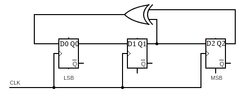
According to figure, we can write next state as: 

$Q_{0N}=Q_1 \oplus Q_2, Q_{1N}=Q_0,Q_{2N}=Q_1$

Transition table can be given as:

Q2 Q1 Q0 Q2N Q1N Q0N
0 0 0 0 0 0
0 0 1 0 1 0
0 1 0 1 0 1
0 1 1 1 1 1
1 0 0 0 0 1
1 0 1 0 1 1
1 1 0 1 0 0
1 1 1 1 1 0

$4Q_2 + 2Q_1+Q_0$ is simply the decimal equivalent of state. Now, transition diagram can be drawn from above table as:

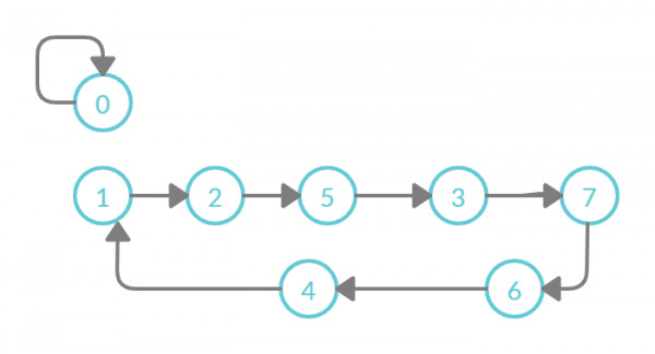
Correct State Sequence: 1,2,5,3,7,6,4.

Option (B) is correct answer.

1 comment

Complete solution.

Very good.
1
1
2 votes
2 votes
Caption

 THE ANSWER IS B.

Answer:

Related questions