We can design a Mealy Machine as per the requirement given in the question.
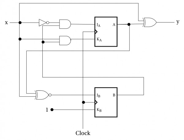
From which we will get state table, and we can design sequential circuit using any Flip-flop from the state table (with the help of excitation table) :
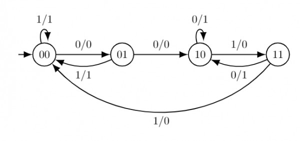
As we get $4$ states (renaming state component to binary states), we need two FFs to implement it.
Let $A$ and $B$ be present states, $x$ be the input and $y$ be the output.$$\small \begin{array}{c|c|c|c|cc|cc|}
\text{Present State}&\text{Input}&\text{Next State}&\text{Output}&\rlap{\text{FF}}&&\rlap{\text{FF}}\\
&&&&\rlap{\text{inputs}}&&\rlap{\text{inputs}}\\
\hline
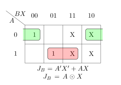
AB&X&A'B'&Y&J_A&K_A&J_B&K_B\\\hline
00&0&01&0&0&X&1&X\\
00&1&00&1&0&X&0&X\\
01&0&10&0&1&X&X&1\\
01&1&00&1&0&X&X&1\\
10&0&10&1&X&0&0&X\\
10&1&11&0&X&0&1&X\\
11&0&10&1&X&0&X&1\\
11&1&00&0&X&1&X&1\\
\end{array}$$ \begin{array}{cc|cc} Q_t&Q_{t+1}&J&K\\\hline 0&0&0&X\\0&1&1&X\\1&0&X&1\\1&1&X&0\end{array}