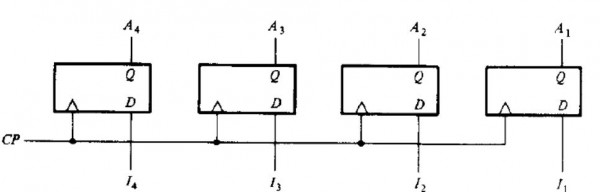
Include a 2-input NAND gate with the register of the figure and connect the gate output to CP inputs of all the flip-flops. One input of the NAND gate receives input from the clock-pulse-generator. Another input of NAND gate provides parallel load control. Explain the operation of the modified register.